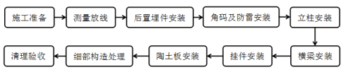
5. Construction process flow and operation points
5.1 Construction process flow
The construction process of this method is shown in Figure 5.1.
The actual position and size of walls, eaves, etc;
(2) Draw the actual exterior elevation of the building using CAD software based on measurement data, and optimize the layout and grid diagram according to the design scheme of the design institute, achieving aesthetics, safety, material efficiency, and facilitating construction and production;
(3) When dividing the layout, priority should be given to controlling the height of the board based on the layer height, and controlling the width of the board based on the door and window openings and corners;
(4) Mark letter codes on each board of different sizes in the drawing, and use the same letter code for boards of the same size.
(5) According to the layout grid diagram, count the number of panels of the same specification, and represent the letter codes, specification dimensions, number of panels, and area in the layout grid diagram in a table format to form a cutting order.
2. Prepare a material entry plan, labor demand plan, and construction schedule plan, and submit them to the supervisor for approval.
3. Organize technical personnel to familiarize themselves with drawings and construction plans, promptly raise and solve problems, and handle process handover procedures with various trades.
4. Based on the on-site conditions, construct and determine temporary production and living facilities, determine the on-site water supply, power supply, and transportation methods, and ensure the stacking and storage of materials and equipment after entering the site.
5. Organize workers to enter the site, conduct three-level safety education, technical briefing, safety briefing, and familiarize themselves with the on-site construction environment.
6. According to the construction conditions, set up or reinforce the scaffolding required for construction, install vertical transportation facilities, and produce the required joint sealing strips for construction.
5.2.2 Grassroots Inspection and Handling
1. Grassroots inspection: The cement mortar leveling layer of the wall should comply with the acceptance standards for general plastering engineering in the "Code for Quality Acceptance of Building Decoration and Decoration Engineering" GB50210-2001, and the insulation mortar base of the outer wall should also comply with the acceptance standards for wall energy-saving engineering in the "Code for Construction Quality Acceptance of Building Energy saving Engineering" GB50411-2007.
2. Grassroots treatment
(1) Inspection and treatment of base smoothness: If the flatness of the wall base and the squareness of door and window openings cannot meet the general plastering requirements, a 1:2 cement mortar or polymer cement mortar should be used for re leveling treatment, and the thickness of the leveling layer should be greater than or equal to 10mm;
(2) Inspection and handling of grassroots defects: If there are hollowing, cracks, and peeling phenomena on the grassroots, use a grinding wheel cutting machine to cut it open, chisel it clean, clean it to the original grassroots, moisten it with water, and level it layer by layer with 1:2 cement mortar.
5.2.3 Measurement and laying out
The construction measurement of the curtain wall should be coordinated with the axis of the main project construction measurement. Horizontal and vertical control lines should be set out on the wall, and then the vertical positioning line of the vertical keel and the horizontal installation control line of each row of embedded parts should be set out according to the construction drawing and layout grid diagram of the ceramic panel curtain wall.
Based on the on-site situation after laying out, measure and review the actual construction of the civil engineering structure. If it is found that there is a large error between the layout and grid diagram and the actual on-site situation, adjustments should be made before proceeding to the next process.
5.2.4 Installation of rear embedded parts
1. Positioning of rear embedded parts
Make a paper embedded part with the same shape and specifications as the rear embedded part using cardboard, draw a vertical centerline on the paper embedded part, align the centerline of the paper embedded part against the wall with the vertical positioning line of the keel, align the upper edge line of the cardboard with the horizontal installation control line of each row of rear embedded parts, and mark the four installation holes with a marker pen.
2. Chemical bolt installation
Drill holes using an impact drill at the designated location, with the aperture and depth determined according to the design drawings; Use a dedicated air cylinder or compressed air machine to clean the dust in the drilling hole. It is recommended to repeat it no less than 3 times, and there should be no dust or water inside the hole; Insert the glass tube anchoring agent with the round head facing inward into the hole and push it to the bottom of the hole. Use an electric drill and specialized installation fixture to forcefully rotate the screw and insert it into the hole. Impact should not be used; When it is screwed to the hole bottom or the marked position on the bolt, stop the rotation immediately, remove the installation fixture, and avoid disturbance after the gel is completely cured.
3. Pull-out test
The depth of chemical bolt implantation and the degree of bolt tightening directly affect the safety of the entire curtain wall. Therefore, it is necessary to verify whether the design strength requirements are met through anchor bolt pull-out experiments. 0.1% of the total number of inspection batches and no less than 5 pieces should be taken, and only after passing the sampling inspection can the embedded parts be installed.
4. Installation of rear embedded parts
Insert the rear embedded parts onto the four anchor bolts, tighten the nuts initially, adjust the surface flatness and verticality of the anchor plate, and then tighten the nuts. After installation, it is necessary to use a torque wrench to check the tightening force of bolts and nuts, which should not be less than 60N · m, and the sampling rate should not be less than 1/3. Spot welding should be carried out to ensure safety and reliability.
5.2.5 Corner code and lightning protection installation
1. Corner code installation
Pop up the corner code installation position line according to the vertical control line. When welding corner codes, the position of the corner code should be aligned with the ink line, and the corner codes on both sides of the same horizontal position should be temporarily spot welded and inspected. Then, the middle corner code of the same column should be spot welded, and the verticality of the same column corner code should be checked and adjusted. After meeting the requirements, full welding of the corner code and embedded parts should be carried out.
2. Lightning protection installation
According to the design drawings or adopted φ The 12 lightning protection connecting steel bars are welded to the rear embedded parts and connected to the main structure lightning protection system. The horizontal spacing of the lightning protection connecting steel bars is not more than 10m.
3. After the installation is completed, the embedded parts and corner code adapters shall be inspected and accepted, and the welding position shall be treated with anti-corrosion and rust prevention.
5.2.6 Column installation
1. The column is made of galvanized square steel. After the column is cut, the bolt holes are positioned according to the corner code adapter, with a positioning deviation of less than 2mm. Then, a bench drill is used to drill the bolt installation holes.
2. First, install the columns at both ends of the wall. After the columns are in place, connect them to the corner fittings using stainless steel bolts. Adjust and fix the positions of the columns according to the vertical line and wall end line, ensuring the distance and verticality between the columns and the wall.
3. The columns are installed layer by layer from bottom to top, and a 5mm thick galvanized steel plate L ≥ 300mm is used as an expansion joint at the joint. The upper end of the steel plate is fixed to the upper column with bolts, and the lower end is inserted into the installed lower column. A 20mm expansion gap is left at the joint of the upper and lower columns.
4. After the installation of the two end pillars is completed, two thin steel wires are pulled in the middle to adjust the overall flatness of the installation of the middle part of the pillars.
5.2.7 Cross beam installation
1. After the installation of the columns is completed, according to the horizontal installation control line, mark the installation positioning lines for each row of crossbeams on the columns in sequence according to the design width and transverse seam width of the clay board. Each row of positioning lines must be closed along the perimeter of the building, and the crossbeams can only be welded after being checked for accuracy.
2. Cross beams are generally made of galvanized angle steel short beams, with a length determined according to design requirements (generally not less than 250mm). After the angle steel is cut, use a bench drill to drill the installation holes for the hanging bolts.
3. Align the crossbeam with the installation positioning line, perform spot welding for temporary fixation, verify the accuracy of the crossbeam position, use a level to check and adjust the flatness, and after passing the inspection, perform full welding for fixation. The installation quality of the crossbeam will directly affect the straightness of the transverse joints in the installation of the clay board, which is a key construction process and must be strengthened in terms of installation quality control.
4. Clean the welding slag at the weld seam, and then apply anti rust paint and protective topcoat to the damaged parts of the weld seam and anti-corrosion layer.
5. After the installation of all crossbeams is completed, a concealed inspection of the keel must be carried out in conjunction with the supervisor and construction unit. After passing the inspection, the installation of hanging parts and clay boards can be carried out.
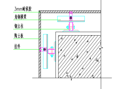
5.2.8 Hanger installation
1. The hanging piece is fixed with bolts and crossbeams. One end of the hanging piece has an adjustable installation hole, and the other end has upward and downward grooves, with the upper groove being half shallower than the lower groove.
2. Use bolts to pass through the mounting holes of the hanging components and fix them to the crossbeam with insulation gaskets. Do not tighten the bolts for now, and wait for the ceramic board to be checked and adjusted for flatness before tightening.
3. According to the design drawings, install the distance between the ceramic clay board and the wall and the wall end line. First tighten the hanging pieces on the left and right sides of the bottom row, then level the control line between the two hanging pieces, and then tighten the bolts of the other hanging pieces in the bottom row in sequence according to the control line.
5.2.9 Installation of clay slabs
1. Set control lines for the straightness and surface smoothness of the joint grid.
(1) Set up a first level installation control line: Weld steel bars and crossbeams at the four corners of the wall facade to be installed, and place thin steel wires between each two steel bars. Adjust the verticality, levelness, and distance between the thin steel wires and the wall according to the vertical and horizontal lines of the wall and the distance between the clay board and the wall.
(2) Setting up vertical seam straightness control line: The vertical line of the first level installation control line is combined with the layout grid diagram to lead out the first column of the vertical seam straightness control line of the clay board. The vertical seam straightness control line is set every 4-6 columns.
(3) Set up a control line for the straightness of the horizontal joint: the horizontal line of the first level installation control line leads out the first row of horizontal joint control line and flatness control line of the ceramic board. The horizontal joint control line and flatness control line move upwards with the installation of each row of ceramic board.
2. Installation of clay board
(1) For the convenience of operation, the ceramic tiles are installed in rows from bottom to top. For each row, the ceramic tiles are installed at the corners first, and then the middle ceramic tiles are installed.
(2) First, use a glue gun to squeeze the weather resistant adhesive into the upper groove of the fastened first row corner. The thickness of the weather resistant adhesive should be half of the groove depth. During the construction process, pay attention to preventing the weather resistant adhesive from contaminating the panel;
(3) Each clay board requires at least four pendants. Insert the first clay board bearing wall into the pendant slot, fasten the upper row of pendants, roughly adjust the position of the clay board, and then tighten the bolts preliminarily;
(4) Adjust the two hanging pieces in the upper row along the vertical wall direction according to the flatness control line. After the panel flatness meets the requirements, tighten the bolts of the hanging pieces in the upper row; Move the panel left and right according to the straightness control line of the vertical seam to align the edge of the board with the control line;
(5) Fix the joint adhesive strip with the same width as the vertical seam tightly against the inner edge of the clay board and fix it on the crossbeam with self tapping screws. The joint adhesive strip should extend into the joint of the board at least 1/3 of the board thickness. The joint adhesive strip should be straightened and continuously set to ensure waterproofing effect;
(6) Install the remaining clay boards in sequence according to the above steps, move left and right to adjust the vertical joints of the boards being installed, and ensure that they can firmly hold the joint rubber strip to avoid excessive force causing displacement of adjacent boards; Correct deviation and reduce error accumulation through the straightness control line of the vertical seam set in the middle. During the installation process, regularly use a 2m ruler to check the flatness of the board surface installation.
5.2.10 Detailed Construction Processing
1. Yin and Yang Corner Structures
In addition to using finished shaped ceramic clay panels at the corners of the curtain wall, on-site splicing methods can also be used.
(1) External corner: Cut the edges and backs of two adjacent ceramic clay boards into a 45 ° chamfer using a cutting machine. First, install the fixed side of the ceramic clay board and evenly apply weather resistant sealant at the joints. Then, install the other side of the ceramic clay board and adjust its position. Leave a 3mm gap at the joint, and the joint should be even. The external corner should be square.
Detailed diagram of the structure of the positive corner
(2) Internal corner: When splicing, apply weather resistant sealant evenly on the edge of one side of the clay board, and directly cover the surface of the installed clay board on the other side. The two boards should not be in direct contact, and gaps should be left according to the width of adjacent board joints. The joints should be even and the internal corner should be square.
2. Partial middle plate repair and installation
First, thread a cotton rope into the middle cavity of the upper and lower sides of the pottery board to be installed. Tie the two ends of the cotton rope tightly on the board surface, lift the upper and lower cotton ropes respectively, tilt the pottery board into the groove of the upper row of hanging parts, and then level it. Slowly release your hand to clamp the pottery board into the groove of the lower row of hanging parts. Move the board left and right to adjust the vertical seam. After installation is completed, loosen the cotton rope and gently pull it out.
3. Structure of door and window opening edges
The edges of door and window openings are made of 3mm thick aluminum veneer, fixed with self tapping screws or plastic expansion bolts. The color of the panel is determined according to the design, and the gaps between each joint are sealed with weather resistant adhesive.
When constructing aluminum veneers for window openings, the construction sequence should be from top to bottom, then left to right; The aluminum veneer along the window sill and door opening should have a 5% external inclined drip slope (i.e. high inside and low outside), and drip holes should be drilled below the aluminum veneer; The lower edge should have a 5% outward sloping water flow slope (i.e. high inside and low outside), and the interface between the aluminum veneer and the edge of the door and window frame around the door and window openings should be sealed with insulation joint strips and weather resistant sealant.
4. Construction of parapet top
If the last row of ceramic tiles on the top of the parapet wall is not a whole board, it can be customized with the manufacturer or cut on-site and installed. When cutting, the panel should be marked first and cut along the line to ensure a straight cut.
The top closure of the parapet wall is made of 3mm thick aluminum veneer, fixed with self tapping screws or plastic expansion bolts. The surface of the aluminum veneer should have a 5% internal diagonal flow slope (i.e. low inside and high outside), and the gaps between each joint should be sealed with weather resistant adhesive.
5. External wall footing structure
Deformation joints should be left at the foot of the exterior wall of the clay curtain wall to avoid direct contact with the ground and ensure that rainwater does not seep into the interior of the curtain wall. The distance between the bottom row of clay plates and the outdoor ground is 15mm. After the gap is filled with foam rods, a weather resistant sealant no less than 3.5mm thick is applied on the surface.
6. Expansion joint construction
At the expansion joint of the wall, finished expansion joint plates should be installed first, and insulation and waterproofing treatment should be done. A column and crossbeam should be installed on both sides of the expansion joint, and the joint of the clay plate should be set between the two columns to prevent uneven settlement and deformation of the building, which may cause the clay plate to rupture.
5.2.11 Cleaning and acceptance
After the installation of the clay board is completed, a systematic inspection should be conducted on the completed surface to check for any contaminated or dirty parts. The contaminated areas should be wiped clean with a cotton cloth dipped in a small amount of cleaning agent, and then wiped again with a clean water cloth; During and after installation, attention should be paid to the protection of finished products, and it is strictly prohibited to step on or hit heavy objects.
(来源:)
江西韶华陶瓷有限换公司立足环保、生态、人文的理念。公司专注于陶土建筑产品的发展,研发,以及创造,主营产品陶板幕墙、陶砖、陶棍、陶百叶等新型外墙装饰建材。
